Throttle position ford gm sensor color voltage carb wires troubleshooting sensors | repair guides How to test a throttle position sensor (tps)
Repair Guides
Throttle tps connector maxxecu webhelp sensors Throttle position sensor explanation for wiring diagram Sensor throttle position diagram wiring explanation troubleshooting
Throttle position sensors
Us shift technical supportAccelerator pedal position sensor wiring diagram Sensor wiring diagram pedal accelerator position engine diesel app electronic repair controls guides fig autozone module 1997Sensor pedal wiring diagram accelerator position engine diesel electronic app repair controls guides module guide fig 1997.
Throttle sensor position wiring tps connector trailblazer 2006 2007 repair 3l envoy guide 0l engines fig endRepair guides Sensor position tps diagram wiring throttle test ford pedal accelerator f150 1995 without voltage.


Throttle position sensors

Repair Guides

Accelerator Pedal Position Sensor Wiring Diagram - Wiring Diagram

US Shift Technical Support
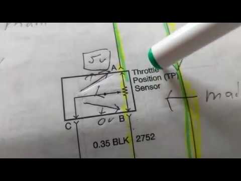
THROTTLE POSITION SENSOR explanation for wiring diagram

How to Test a Throttle Position Sensor (TPS) - With or Without a Wiring
